Explore the circuit
Tinkercad was used to explore the prototype before the documented hardware build. The case separates that planning activity from the original photograph of the assembled circuit.
CEIS101 / COMPLETED ACADEMIC PROJECT
Connecting physical inputs to useful behavior.
A hands-on Arduino project exploring door state, distance sensing, light detection, and simple automated responses.
DeVry University courseworkTHE OBJECTIVE
A small automation system must translate changes in the physical environment into understandable feedback. The project built that connection incrementally through sensors, indicators, and code.
The smart-home project is a tabletop Arduino prototype. It brings together circuit planning, breadboard assembly, programming, and observation of physical inputs. The word security describes the educational project theme; it is not a claim that the build is a certified home-security product.
THE WORK
Door · Distance · Ambient light
Arduino logic
LED indicators · Serial output
IMPLEMENTATION DETAIL
Tinkercad was used to explore the prototype before the documented hardware build. The case separates that planning activity from the original photograph of the assembled circuit.
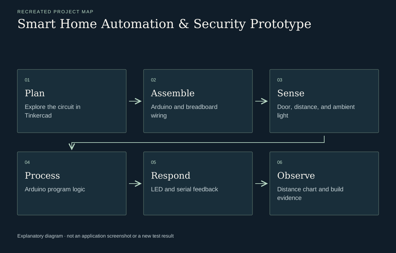
Door-state, ultrasonic-distance, and light inputs are connected to LED feedback, serial output, and light-responsive behavior in the documented stages. The learning task is to explain the path from an input to an observable response.
The presentation combines hardware photographs, circuit views, Arduino code screenshots, and a distance-data chart. These different artifacts help relate the wiring, program logic, and observed output without treating a photograph as a complete functional test.
VISUAL GUIDE
PROJECT EVIDENCE
A completed prototype presentation with original hardware photographs, circuit views, Arduino code screenshots, and sensor-output evidence.
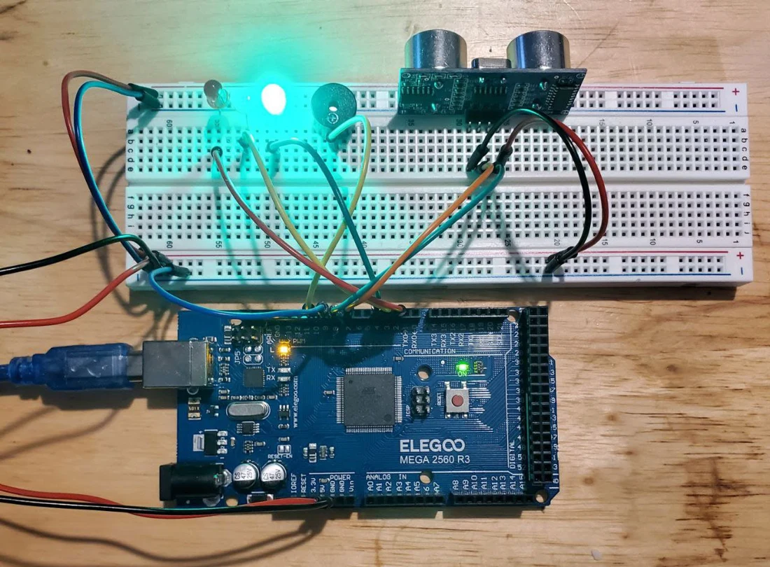
Evidence reviewed: CEIS101 final project presentation. Source pages 4–5, 8–10, 12–26.
The retained image shows the actual Arduino and breadboard build from the presentation.
The source presentation records the circuit exploration and Arduino implementation.
Serial-monitor material and a distance-data chart document the original observations.
WHAT I LEARNED
Incremental builds make hardware debugging easier: check the wiring, confirm the input in the serial monitor, and then add the response logic.
Hardware work requires checking both a physical connection and the program’s interpretation of it. This project makes that relationship visible through staged builds and several forms of evidence, rather than relying on a finished-looking device photo alone.
WHAT THIS DEMONSTRATES
Connecting hardware inputs, program logic, and observable behavior.
Project deliverable: An incremental sensor-and-indicator prototype, documented with hardware photos and code.
REVIEW BOUNDARIES
Completed tabletop prototype for educational use. Original hardware photographs document the coursework; product certification and home deployment are outside its scope.
Based on the original project presentation, reviewed October 17, 2026. Historical project evidence; not a new execution test.